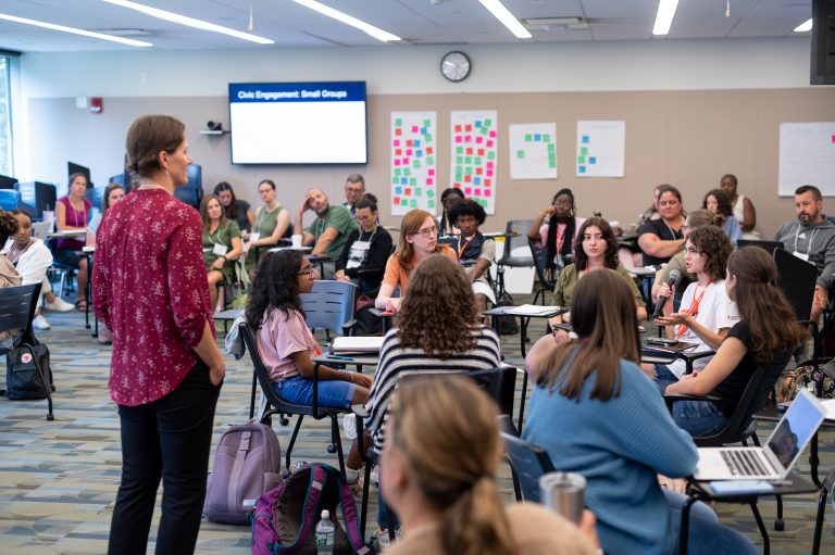
Dodd Human Rights Impact Programs foster a culture of human rights at UConn, in Connecticut, and around the world through outreach and engagement. We develop and support programs and initiatives that seek to directly impact communities by helping them meet their human rights challenges.


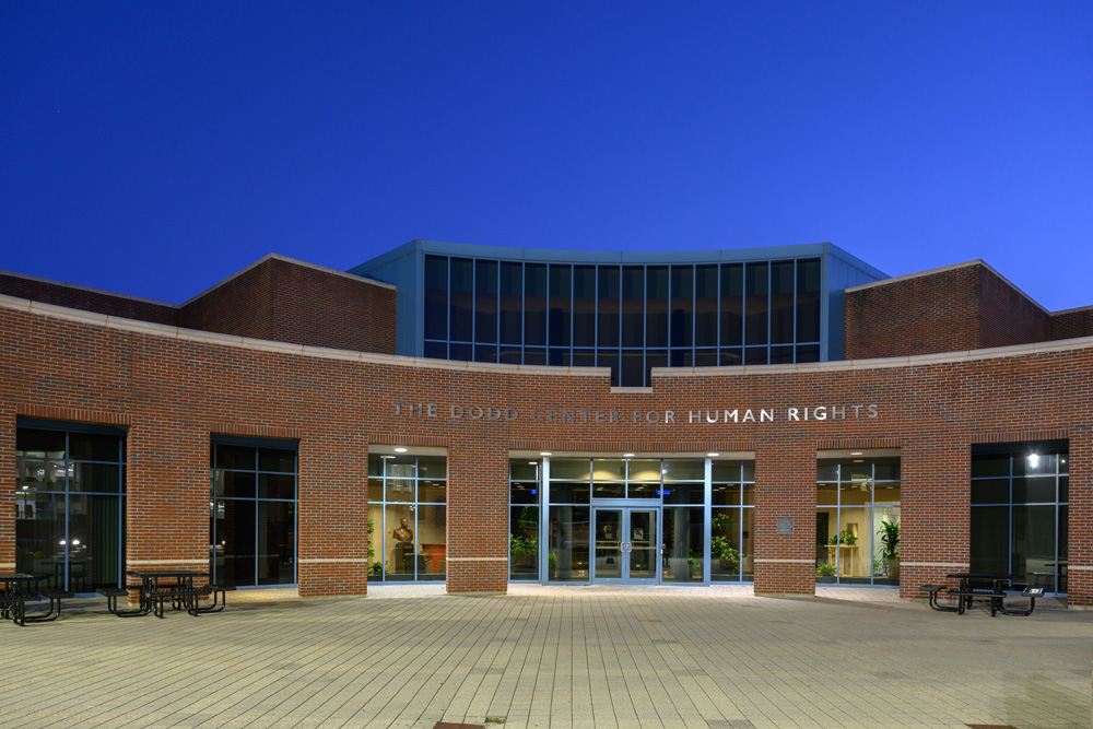
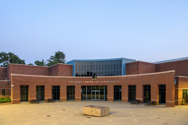
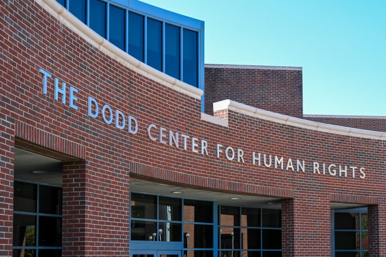
The Dodd Center for Human Rights
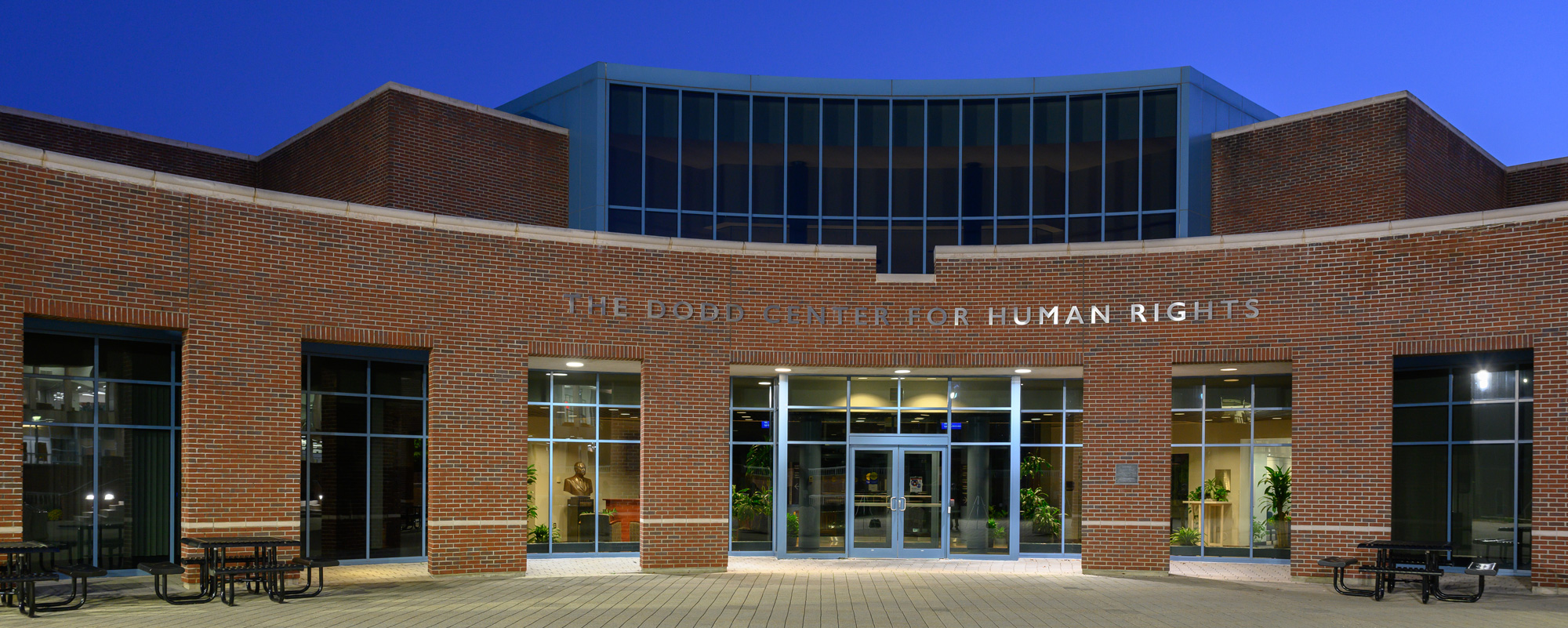
The Dodd Center is a building in the center of UConn’s Storrs campus that houses the Gladstein Family Human Rights Institute, the University Library’s Archives & Special Collections, and the Center for Judaic Studies & Contemporary Jewish Life. It hosts exhibitions, events, and other activities for the campus community and broader public.